Seiko S651 Manuel d'utilisateur
Naviguer en ligne ou télécharger Manuel d'utilisateur pour Imprimantes d'étiquettes Seiko S651. Seiko S651 User`s manual Manuel d'utilisatio
- Page / 58
- Table des matières
- MARQUE LIVRES
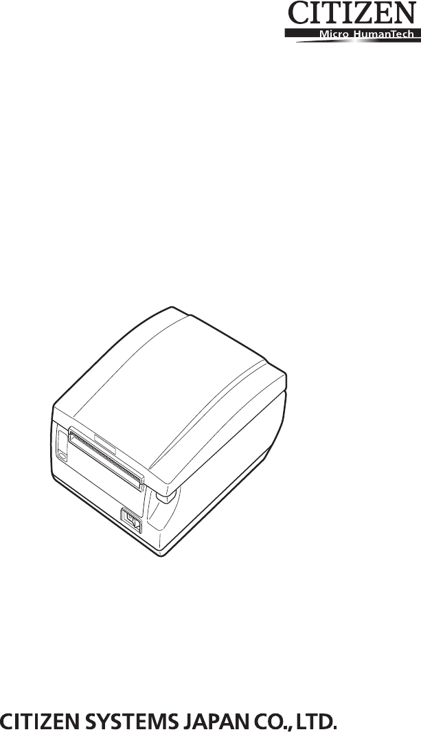
- LINE THERMAL PRINTER 1
- WEEE MARK 2
- Declaration of Conformity 3
- GENERAL PRECAUTIONS 4
- SAFETY PRECAUTIONS 5
- DAILY MAINTENANCE 10
- THE TABLE OF CONTENTS 11
- 1. GENERAL OUTLINE 12
- 1.2 Unpacking 13
- 1.3 Model Classification 13
- 1.4 Basic Specifications 14
- 2.1 Printer Appearance 15
- PAPER LED (orange) 16
- ERROR LED (red) 16
- FEED button 16
- POWER LED (green) 16
- 2.2 Inside the Paper Cover 18
- 2.3 Other Built-in Functions 19
- 3. SETUP 21
- 10/100BASE 22
- 3.3 Bluetooth Interface Board 24
- Changing network settings 28
- Panel button 29
- USB port 29
- LED Functions 30
- 3. Wired/Wireless LAN status 30
- 1. Start up a web browser 31
- Horizontal position 35
- Vertical position 35
- 3.8 Partition for Paper Roll 36
- Interface Board 37
- * Approximately 23 18/12 38
- 3.11 Loading Paper 39
- Power switch cover 40
- CT-S651IIS 41
- 3.15 Installing a Driver 42
- 4.1 Periodic Cleaning 43
- Protective sheet 45
- Front cover release button 45
- Cutter gear 45
- Front cover 45
- Auto cutter blade 45
- 4.4 Self test 46
- 4.5 Hexadecimal Dump Printing 47
- 4.6 Error Messages 48
- 5. OTHER 50
- 5.2 Printing Paper 51
- Selectable item 52
- Selection 52
- Memory switch initialization 54
- CT-S651II_UM_100EN 58
- A82135E-1504 58
- April 2015 58
Résumé du contenu
LINE THERMAL PRINTERMODEL CT-S651 Type IIUser’s Manual
—7—CAUTIONTo prevent injury and printer failures from worsening, observe the following: While the paper cover is open, be careful to not touch the ma
—8—1. GENERAL OUTLINE...91.1 Features...
—9—The CT-S651II line thermal printer series is designed for use with a broad arrayof terminal equipment including data, POS, and kitchen terminals.Th
—10—Make sure the following items are included with your printer.Model numbers indicate printer features according to the following system.Certain com
—11—1.4 Basic SpecificationsItem SpecificationsModel CT-S651IIPrint method Line thermal dot print methodPrint width *1 80 mm/640 dots, 72 mm/576 dots,
—12—Notes:*1: When paper width is 83, 80, 60, or 58 mm.*2: The number of printable columns is selected using a memory switch.The numbers of columns no
—13—Operation panel POWER LED (green)Lights when the power is on, turns off when the power is off.Flashes when data is incoming or a memory error has
—14—Rear connectors Interface connector (serial, parallel, USB, etc.)Connects to the interface cable.The serial interface board is equipped with a DI
—15— PlatenFeeds the paper.Do not remove the platen except to do maintenance. Paper near-end sensor (PNE sensor)Detects when the paper is near the e
—16— Paper end sensor (PE sensor)Detects when there is no paper. Printing stops when this sensor detects thereis no paper. BuzzerBuzzes when errors
WEEE MARKEnWenn Sie dieses Produkt entsorgen wollen, dann tun Sie dies bitte nicht zusammen mit demHaushaltsmüll. Es gibt im Rahmen der WEEE-Direktive
—17— Auto side shift (MSW8-6)This function dissipates heat load during frequent heat generation by a verticalruled line or other specific head heatin
—18—1. Turn off the power.2. For the built-in power type printer, connect the AC power cord to the AC inlet, andinsert the plug into an electric out
—19—1. Turn off the power.2. Orient the interface cable correctly and insert it into the interface connector.3.2 Connecting Interface Cables10/100BASE
—20—Use a serial interface cable with the connection layout shown below.]CAUTION Always unplug the AC adapter from the printer before connecting thep
—21—Bluetooth status LED The LED on the Bluetooth interface board on the rear of the printer indicates thestatus below. Pairing operationYou need to p
—22—B: Configuring pairing settingsNormally, selecting the printer during device detection will transition directly topairing settings.The operation r
—23—This section provides an overview of the Ethernet (LAN) interface board. For detailsabout this board, refer to the separate manual.Panel button op
—24—LED FunctionsThe tables below explain how to interpret LED indications.1. Network transmission speed2. Network status3. Board statusTransmission s
—25—Changing network settingsYou can use a web browser to access a special settings page to check and changeboard settings. Accessing the special set
—26—This section provides an overview of the wireless LAN interface board. For detailsabout this board, refer to the separate manual.Connecting USB do
Declaration of ConformityThis printer conforms to the following Standards:The Low Voltage Directive 2006/95/EC, the EMC Directive 2004/108/EC, the RoH
—27—LED Functions The tables below explain how to interpret LED indications.1. Wired LAN transmission speed2. Wired LAN connection/transmission status
—28—Web ManagerThe wireless LAN interface board has a Web Manager function that can be used toconnect to the board with a web browser and change board
—29—CONFIG ScreenThis will display the Login dialog box shown below. Log in as an administrator andthen configure wireless LAN interface board setting
—30—1. Turn off the power.2. Confirm the orientation of the cash drawer kick-out cable connector and connect itto the cash drawer kick-out connector a
—31—(1) Connector pin configuration(2) Electric characteristics1) Drive voltage: 24 VDC2) Drive current: Approx. 1 A max. (not to exceed 510 ms.)3) DR
—32—This printer can only be positioned horizontally. It cannot be positionedvertically or on a wall.3.7 Precautions for Installing the PrinterCAUTION
—33—Set the partition to the width of the paper roll you are loading.The partition is set at the factory to the position shown below. For 3-inch type
—34—1. Turn off the printer and unplug the power cord from the electric outlet.2. Remove the mounting screws of the serial interface board.3. Remove t
—35—Change the settings of the paper near-end sensor to set the position at whichthe near-end of the paper is detected.1. Use a pointed object, such a
—36—1. Turn on the power.2. Press up on the cover open button to open the paper cover.3. Load the paper roll so that the printable side of the paper i
—1—GENERAL PRECAUTIONS Before using this product, be sure to read through this manual. Afterhaving read this manual, keep it in a safe, readily acce
—37—Attach this cover to prevent the power switch from being used.1. Press the power switch cover onto the power switch compartment until it clicks.Pu
—38—Attach the interface cover to the back of the printer.The shape of the interface cover is different depending on the type of powersource.1. Press
—39—Drivers are included on the CD-ROM that comes with the printer.Install the driver required by your printer.For information about driver installati
—40—A dirty print head or platen may reduce printing quality or cause malfunctions.We recommend cleaning the printer periodically (every 2 to 3 months
—41—The ERROR LED flashes and the auto cutter blade remains extended because aforeign object or paper jam is obstructing it.If the ERROR LED is flashi
—42—5. Lift the protective sheet and turn the cutter gear in the direction of arrow B to returnthe auto cutter to a position where the paper cover can
—43—While paper is loaded, press and hold the FEED button while turning the poweron. Hold the FEED button down for about one second and then release i
—44—Print received data in hexadecimal. If problems such as missing or duplicateddata occur, this function allows you to check whether or not the prin
—45— Paper-endThe end of the roll of paper is detected at two stages, paper near-end andpaper-end.When paper near-end is detected, the PAPER LED ligh
—46—The status display for various messages is shown below.Notes:*1: If the paper cover or front cover is open in standby.*2: If the paper cover or fr
—2—Before using this product for the first time, carefully read these SAFETY PRECAUTIONS.Improper handling may result in accidents (fire, electric sho
—47—(Unit: mm)5. OTHER5.1 External Views and DimensionsBuilt-in power supply typeAC adapter type19231145140 1551614219231145114
—48—Use the paper shown in the following table or paper of the same quality.(Unit: mm)5.2 Printing PaperPaper type Product nameRecommended thermal rol
—49—Memory switches are used to set various printer settings. The memory switchescan be set manually (set by hand on the printer) or by commands. This
—50—Individual setting modeSet the memory switches individually.Do the settings while confirming the memory switch function and settings onthe printou
—51—5. Press the FEED button for at least two seconds.A setting for the memory switch is printed, through the cycle, each time the FEEDbutton is press
—52—The function of each memory switch is shown in the following table. (Shadedvalues are factory settings.)Switch no. Function OFF ONMSW1-1 Power ON
—53—MSW6-1 Act. For Driver Invalid ValidMSW6-2 Character SpaceInvalid ValidMSW6-3 USB Power Save InvalidValidMSW6-4 ReservedFixed —MSW6-5 ReservedFixe
—54—*1: If print data is very dense, the print head is hot, data transmission is slow, or some other conditions, themotor and printing may occasionall
CT-S651II_UM_100ENA82135E-1504April 2015
—3—PRECAUTIONS ON PRINTER INSTALLATIONWARNING Do not use or store this product in a place where it will be exposed to:* Flames or moist air.* Direct
—4—CAUTIONDo not use the printer under the following conditions. Avoid locations subject to vibration or instability. Avoid locations where the prin
—5—PRECAUTIONS IN HANDLING THE PRINTERWARNINGPlease observe the following precautions for power source and powercord: Do not plug or unplug the power
—6—CAUTIONCaution label is attached in the position shown in the following figure. Carefully readthe handling precautions before using the printer.
Produits connexes et manuels pour Imprimantes d'étiquettes Seiko S651
 (1 pages)
© 2020, manymanuals.fr. Tous droits réservés | 1.296 s |
 Manymanuals.com
 Manymanuals.de
 Manymanuals.fr
 Manymanuals.it
 Manymanuals.pl
 Manymanuals.cz
 Manymanuals.es
 Manymanuals-pt.com
Commentaires sur ces manuels